Control Principle And Application Of Side Trimming Disc Shear in Pickling Line As Part Of Coil Slitting Machine
May 21, 2026
Foreword
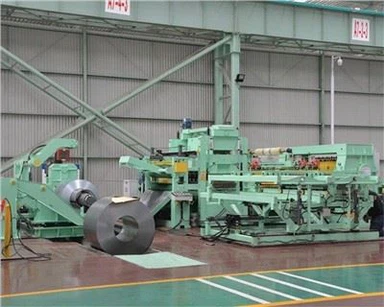
The disc shear is an indispensable piece of cutting equipment in plate and strip production workshops. This shear features two disc-shaped blades, which are used for longitudinally trimming the edges of steel plates and strips, or for slitting them into narrow strips, similar to a coil slitting machine. This shear is widely used for the longitudinal shearing of steel plates and thin strips with a thickness of less than 20 to 30 mm. Because the blades are rotating discs, it can continuously shear moving steel plates or strips in the longitudinal direction. A continuous pickling line in a certain steel plant was put into production in June 2012, employing a passive tension‑shear disc shear. This paper focuses on the basic structure, process, and control principles and characteristics of the disc shear for reference.
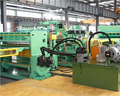
Structure of Disc Shear
The main body of the rotary shear contains no internal drive mechanism; instead, the rotation of the blades is driven by the moving steel strip itself, which is under tension, thereby achieving a "pull-shearing" action. To ensure that the main body of the steel plate remains level as it exits the rotary shear-while the severed edge is allowed to curl gradually-the diameter of the upper blade is designed to be slightly smaller than that of the lower blade.
Concurrently, this design prevents the severed edge strips from curling excessively. To prevent the steel plate from warping as it enters the rotary shear, pressure rollers are installed immediately upstream of the blades. Furthermore, to minimize friction between the steel plate and the cutting edges of the rotary blades, each pair of blades is set at a slight angle relative to the centerline of the steel strip. The primary structural components of the unit include a fixed support frame, a blade gap adjustment mechanism, and a blade replacement device.

Key Parameters and Process Flow
Main Performance Parameters of the Rotary Shear
Material to be sheared: Standard cold-rolled steel sheet
Steel sheet strength:
< 700 MPa
Steel sheet thickness: 1.2–6 mm
Shearing speed:
30–350 m/min
Shearing width:
5–30 mm

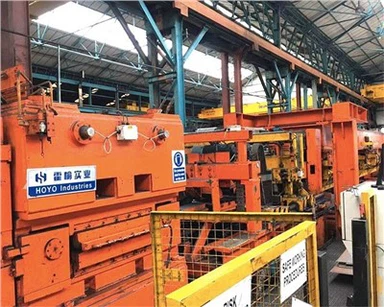
The rotary shear is positioned downstream of the crescent shear; it employs a non-driven rotary structure and is utilized to trim the edges of the steel strip to a specified width. Two sets of cutter heads are mounted on the shearing frames located on either side of the processing line. These shearing frames can be rotated 180 degrees via a rack-and-pinion mechanism driven by hydraulic cylinders. Once a shearing frame has rotated into position, a locking mechanism-actuated by a hydraulic cylinder-engages to secure the frame in place. While one set of cutter heads is actively performing shearing operations, the other set remains available for maintenance, replacement, or adjustment. Width adjustment of the shearing frames is achieved by driving a ball screw via a geared motor, causing the frames to slide along guide rails mounted on the base. Once the desired width setting is reached, the frames are locked into position using threaded hydraulic cylinders.
A pair of pinch rollers and support rollers is positioned at the cutter head inlet. The pinch roller assembly is driven by hydraulic cylinders and serves to prevent strip flutter while supporting the strip, thereby ensuring shear quality. Scrap generated by the rotary shear is directed via a chute into a scrap chopper for edge chopping. Following the chopping process, the scrap is conveyed via a chute into the exit scrap transport system.
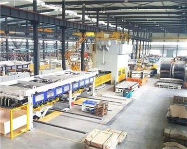
Control System Overview
The basic automation system for the MaSteel pickling line consists of components such as PLCs (Programmable Logic Controllers), an HMI system, an Industrial Ethernet network, fieldbuses, remote field I/O stations (ET200), and programming devices, as illustrated in Figure 2. For this specific unit, the Siemens SIMATIC S7-400 was selected to serve as the controller. The entire unit is equipped with three PLCs, each utilizing a CPU416-2 module. The system's HMI interface is powered by the Siemens WinCC system, with the PLCs connected to the WinCC server via an Industrial Ethernet network. Communication between the PLCs and field devices is conducted using the PROFIBUS DP protocol; each PLC features multiple PROFIBUS DP interfaces dedicated to connecting remote I/O modules, drive systems, encoders, field instrumentation, as well as CPC and EPC devices. The rotary shear control system, akin to that of a coil slitting machine, is managed by a single CPU416-2 module-interfacing with two separate PROFIBUS DP networks-to execute functions including frame width adjustment, overlap adjustment, and side clearance adjustment.
Control of the Rotary Shear
Description of Control Modes
The rotary shear system encompasses the rotation of the shear frame, adjustment of the frame width, adjustment of the blade overlap, and adjustment of the blade side clearance. Control is available in two modes: manual and automatic.
Manual Control
The manual mode is primarily utilized for operations during debugging and fault conditions; buttons located on the control console allow for the independent control of the rotary shear's various adjustment mechanisms, locking mechanisms, and cutter head rotation movements. The operational procedure for rotating the cutter head is as follows: when the rotary shear is not in use or the exit unit has come to a halt, pressing the start button causes the rotary shear frame and the scrap chopper frame to retract by an appropriate distance. This retraction prevents the steel strip from interfering with the rotation process, while also ensuring that the scrap chopper does not obstruct the rotation of the rotary shear. Subsequently, the rotation locking device disengages, and the frame-depending on its current position-rotates 180 degrees (either clockwise or counter-clockwise); once the rotation is complete and the frame reaches its designated position, the rotation locking device re-engages to secure it. The operational procedure for retracting the rotary shear from the production line is as follows: when the rotary shear is not in use or the exit unit has come to a halt, pressing the start button causes both the rotary shear frame and the scrap chopper frame to retract to their respective standby positions.
Automatic Control
In automatic mode, the control of the rotary shear-a function also found in a coil slitting machine-is executed via an automated sequence based on status information from the main controller and the start signal. For two consecutive steel coils-a preceding coil and a succeeding coil-the operation mode of the rotary shear can be categorized into four scenarios: Not Used–Not Used (NU-NU), Used–Used (U-U), Used–Not Used (U-NU), and Not Used–Used (NU-U).
NU-NU
The rotary shear requires no adjustment.
U-U
The course of action is determined by the differences in width and thickness between the preceding and succeeding steel strips. If the parameters are identical, the rotary shear requires no adjustment; if they differ, the automated sequences for adjusting the shear width, overlap amount, and side clearance are invoked.
U-NU
The automated sequence for adjusting the shear width is invoked to widen the rotary shear frame to its standby position.
NU-U
First, the automated sequence for moving the rotary shear to its standby position is invoked; subsequently-once the weld seam has come to a halt at the rotary shear's location-the automated sequences for adjusting the shear width, overlap amount, and side clearance are invoked.
Optimization of the Mechanical Clearance Elimination Function for the Rotary Shear

The rotation of the motor drives the lead screw, which simultaneously drives the encoder; this motion is converted into the lateral displacement of the rotary shear holder, thereby enabling the adjustment of the rotary shear's side clearance. Due to the inherent clearance between the nut and the lead screw, when the direction of rotation switches from forward to reverse, the lead screw and encoder initially rotate together while the nut remains stationary, resulting in a lack of movement in the shear holder. This phenomenon-where the position sensor detects a change in position even though the actual physical position has not changed-is caused by the mechanical backlash within the equipment. Since the encoder was calibrated in the "closing" direction, the equipment's final movement is consistently executed in the closing direction to eliminate the position control errors caused by the aforementioned mechanical backlash. For instance, to move from the current position (Point A) to Point C, the mechanism is first opened to Point B and then closed to Point C.
To achieve high control precision, the adjustment of the overlap and side clearance for the rotary shears-as well as the clearance adjustment for the scrap chopper-employs the following method: whenever the target value exceeds the current value, the distance is first adjusted to a value slightly greater than the target, and is then slowly closed back down to the target value. We have incorporated a program block for automatic clearance adjustment into the PLC software; by integrating this with the control logic of the original design and applying the principles of closed-loop control systems-specifically through real-time monitoring via absolute encoders-we have successfully achieved not only real-time feedback on the mechanical clearance of the rotary shears but also the precise, automatic adjustment of that clearance. Since the implementation of these improvements, the accuracy of the clearance adjustment has fully met production requirements, significantly boosting production efficiency and ensuring both the quality and smoothness of the shearing process.
Conclusion
On-site production results demonstrate that the control system for the Ma Steel pickling line's rotary shear is automated, reliable, and easy to operate, while also reducing labor intensity. It has improved shearing quality and production efficiency, effectively meeting production requirements and generating significant economic benefits.